- Have any questions?
- +1 (781) 656 7962
- support@cheapnursingpapers.com
Complete Multism Circuits and Lab Work NEED A MULTISM EXPERT
COMPLETE TWO PART ASSIGNMENT….PART 1 AND LAB PART 2
PART 1:
Fundamental Properties of AC Circuits/Lab
RC and L/R Circuits
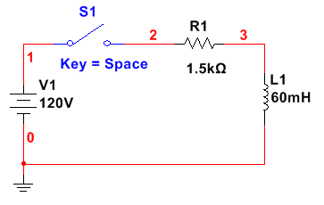
- Consider the series L/R circuit below:
- What is the time constant of the circuit with S1 closed?
- What is the eventual steady-state current with S1 closed?
- What is the value of the circuit current at the first instant S1 is closed? (t = 0s)
- What is the value of the circuit current exactly one time constant after S1 is closed?
- How long after S1 closes will it take before the circuit current reaches its steady-state value?
- For the same circuit, assume that the switch S1 has been closed for more than five L/R time constants. If a 1MΩ resistor is placed across the terminals of the switch, calculate:
- The approximate time constant of the circuit with S1 open.
- The peak inductor voltage VL, when S1 is opened.
- The di/dt value the instant S1 is opened.
- How long it takes for the current to decay to zero after S1 is opened (approximately).
Series L/R Circuit:
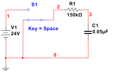
- Consider the series RC circuit below:
- Assume C1 is completely discharged with S1 in the position shown. If S1 is moved to the top position, how long will it take for the capacitor voltage to reach
- 3V
- 6V
- 15V
- 20V
- Assume that C is completely discharged with S1 in the position shown. If S1 is moved to the top position, how much is the resistor voltage at the following time intervals?
- t = 0 s
- t = 4.5 ms
- t = 10 ms
- t = 15 ms
- t = 25 ms
- Assume that C is fully charged with S1 in the top position. If S1 is moved to the bottom position (as shown), how long with it take the capacitor to discharge to:
- 4 V
- 8 V
- 12 V
- 18 V
Series RC Circuit:
- Assume C1 is completely discharged with S1 in the position shown. If S1 is moved to the top position, how long will it take for the capacitor voltage to reach
LAB PART 2:
Fundamental Properties of AC Circuits/Lab
Series L/R and RC Circuits
- Watch the video
- Week 6 Video Lecture – Multisim Series RL
- Construct the series L/R and RC circuits from this week’s assignment in MultiSIM and perform Transient Analysis on each circuit to confirm your calculations. Use a 5% tolerance for all of the components. Capture a screenshot of the output of the analysis to confirm your calculations. Create a table to demonstrate your expected and measured values.
- Include a discussion of the following:
- Differences between the calculations and the simulations.
- How would you go about designing a circuit with an applied voltage of 24V and a resistor of 1kohms such that the current in the circuit starts out at 0A and reaches 24mA in 2 seconds?
- How would you go about designing a circuit with an applied voltage of 24V and a resistor of 1kohms such that voltage starts out at 0V and reaches 24V in 2 seconds?
"Get 15% discount on your first 3 orders with us"
Use the following coupon
FIRST15
Order Now
Hi there! Click one of our representatives below and we will get back to you as soon as possible.